Background
Client: Undisclosed – Leading UK-based Energy Solutions Provider
Industry: Power Generation
Location: Somerset (South West, UK)
Date: January 2025
Introduction
Reliable power infrastructure relies on robust earthing systems to safely manage fault currents, minimise operational risks, and comply with industry regulations. This case study outlines our approach for an earthing system design at a new peak lopping station site in the UK. The goal was to deliver a safe, compliant, and future-proof design for a power generation project.
Key Takeaways
- Project Background
- Scope of Work
- Our Methodology
- Key Safety Measures & Recommendations
- Further Results & Outcomes
Project Background
The client is a leading energy solutions provider specialising in the design, construction, and maintenance of electrical power systems. Their operations include complex site installations that demand rigorous safety testing and compliance with national and industry standards.
For this project, their site was set to accommodate a new peak lopping station, including high-voltage (HV) equipment and generators. This necessitated a detailed earthing study for:
- An 11kV Distribution Network Operator substation
- A client-operated 11kV switchroom
- Three gas generators within the compound
Their site was at the pre-construction stage with no pre-existing electrical earthing infrastructure, meaning our design had to be built from scratch.
Scope of Work
EPS was engaged by the client to design an electrical earthing system that provides a cost-effective solution which operates in a safe and compliant manner.
Our scope of work included:
- Soil resistivity testing
- Calculation of ground return currents
- Designing an effective earth electrode system
- Making sure step and touch voltages around the compound remain within tolerable limits
- Performing Earth Potential Rise (EPR) calculations
- Verifying whether the site was ‘HOT’ or ‘COLD’ to guide subsequent safety measures that should be followed
- Determining whether the site is safe to energise
Methodology
Regulatory Standards & Guidelines
| Industry Standard | Definition |
|---|---|
| BS7430:2011+A1:2015 | Code of Practice for Protective Earthing of Electrical Installations. |
| BS EN 50522 | Earthing of power installations exceeding 1kV (AC). |
| ENA Technical Specification 41-24 Issue 2 | Guidelines for the Design, Installation, Testing, and Maintenance of Main Earthing Systems in Substations. |
| IEEE 80:2013 | IEEE Guide for Safety in AC Substation Grounding. |
| IEC 62305 | Protection Against Lightning. |
| ENA Engineering Recommendation EREC S34 | A Guide for Assessing the Rise of Earth Potential at Substation Sites. |
| TG-NET-SST-005 | Secondary Distribution Substations; Common Clauses – Design and Installation Standard. |
Soil Resistivity Testing
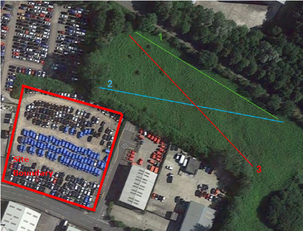
This testing was essential for understanding the soil’s resistivity and allowed us to optimise the client’s system design accordingly. Our power system consultants leveraged the Wenner four-pointed method to measure soil resistivity across three traverses surrounding the site. We then processed the data using CDEGS (Earthing Modelling Software) via the RESAP module, which produced an accurate three-layered soil model of the client’s site.
Discover: What is soil resistivity testing, and why is it important for earthing design
Earthing System Design
We also used CDEGS (MALZ) to model the site’s earthing grid with key design elements including:
- Ground impedance which was calculated at 0.224 ohms in Isolation.
- A fault current of 1.25kA, based infeed fault level and Ground Return Current (Igr)
- A 1-second disconnection time for Touch / Step Safety Assessments.
Furthermore, the 11kV cable infeed’s were also considered along with the impedance of the upstream primary substation. This approach ensured an accurate split of the ground return current, reflecting the portion flowing through the below-earth electrode and the armouring of connected infeed cables.
Earth Potential Rise (EPR) and Voltage Safety Assessment
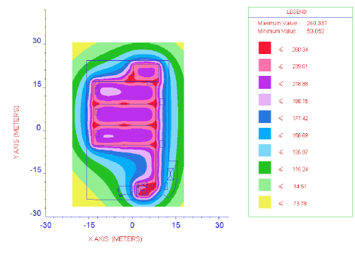
We calculated a 279.52V earth potential rise at the site during a high voltage (HV) earth fault which was well below the threshold of 430V. This allowed our experts to deem the site as ‘COLD’. Furthermore, we confirmed that it was safe for the client to integrate both high-voltage (HV) and low-voltage (LV) earthing systems into their operations. We also found that the touch voltage within the compound was 226.21V, falling safely within the 233V limit for a 1-second disconnection time.
Further Reading: Find out why Earth Potential Rise (EPR) should never be forgotten during earthing design.
Further Recommendations and Key Safety Measures
To ensure operational safety and regulatory compliance, the following measures were implemented:
- To avoid hazardous touch potentials outside the compound, the perimeter fence was not bonded to the Main Earthing System (MES).
- Extraneous conductive parts that are bonded to the MES were placed at least 2 metres away from the perimeter fence.
- Where 2-metre segregation was not feasible, we recommended implementing insulating panels to prevent hazardous voltage fluctuations.
- Assessment of electrode CSAs to ensure adequate short circuit withstands.
- Assessment of surface current density of installed electrode to ensure maximum fault current can be effectively dissipated without causing soil to dry out.
Results and Outcomes
To summarise, our electrical earthing experts successfully met all project requirements to ensure safety and compliance across the client’s electrical infrastructure. Notably, we determined that their site was in fact ‘COLD’, deeming it safe prior to energisation while providing them with a comprehensive earthing grid design that adheres to the ENATS 41-24 requirements.
Our final recommendations included post-installation verification and the completion of an “As-Built” earthing layout to confirm the installed system’s performance.
Tailored Electrical Earthing Solutions for Your Operations
From soil resistivity testing to in-depth safety analysis, we design electrical earthing systems that meet your project requirements and comply with recognised industry standards. Whether you’re embarking on a new project or enhancing existing infrastructure, our expertise guarantees optimal performance and operational safety.
Let’s discuss how we can support your next energy project.